


Engineering machine pin shaft shafts are connecting elements between mechanical parts and components, which are subjected to large unidirectional bending loads, shear stresses or extrusion stresses. Engineering machine pin shaft in the work or walking device in the two relative moving parts articulation of the main form, in the machine work process, the pin bearing is subject to a large reciprocating cycle of shear force, in the work is prone to fracture failure, resulting in greater economic losses A construction machinery pin shaft is welded by 40Cr steel shaft and Q235B steel casing, poor service conditions, long-term exposure to moisture and cement dust environment, fracture occurs after 3 months. In order to find the cause of the pin shaft fracture, the researchers conducted physical and chemical inspection and analysis to help improve the welding process and prevent the pin shaft fracture.
1. Physicochemical testing
1.1 Macro observation
The construction machinery pin shaft broke at the welding of the 40Cr steel shaft and the Q235B steel casing, and the 40Cr steel shaft was divided into two parts along the fracture surface, and the two side sections were called section A and section B respectively. As can be seen from the macroscopic morphology of the fracture shown in Figure 1, the crack source is located at the weld weld, extending along the cross-section of the 40Cr steel shaft, and the macroscopic flatness of the fracture is radial, with obvious brittle fracture characteristics.
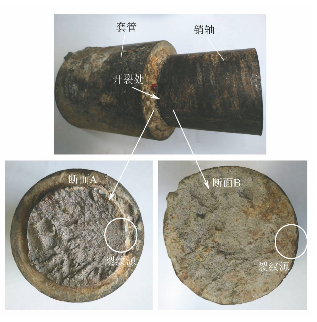
Fig. 1 Macroscopic morphology of a broken pin shaft
1.2 Chemical composition analysis
The chemical composition analysis of the sampling of the fractured pin shaft shows that its chemical composition meets the requirements of GB/T3077-2015 "Alloy Structural Steel" for 40Cr steel composition, but the content of impurities such as phosphorus and sulfur is relatively high, although it does not exceed the standard requirements but is higher than the internal control requirements in normal production (the mass fraction of phosphorus is ≤ 0.020%, and the mass fraction of sulfur is ≤0.015%).
1.3 Metallographic testing
Cut longitudinally from section B along the crack source, make a rectangular block specimen, and observe its microstructure after polishing and erosion. Anomalous tissues with different degrees of leaching and coloring than the base metal were found near the crack source in its upper right corner, as shown in Figure 2.
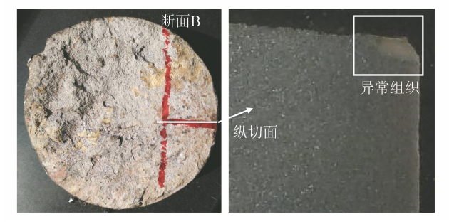
Fig. 2 Sampling location and abnormal organization
Further magnification can be seen that the abnormal tissue near the crack source is the weld heat affected zone tissue dominated by martensitic, and the microstructure in the base material region is ferrite + pearlite, as shown in Figure 3.
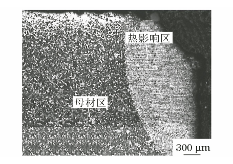
Fig. 3 Microstructure morphology near the crack source
Cutting the specimen with weld seams on the cross-section and observing its microstructure morphology, as shown in Figure 4, it can be seen that the specimen has typical weld morphological partitions with clear interfaces, including weld areas, heat affected regions, and base metal regions.
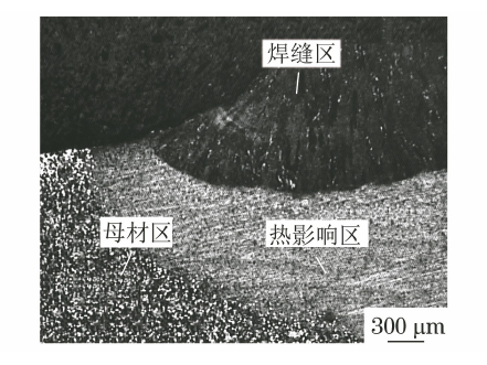
Fig. 4 Microstructure topography near solder joints
Further observation of the microstructure morphology of the heat affected region, as shown in Figure 5, it can be seen that the tissue close to the weld area in the heat affected region is a coarse martensitic body, which is the superheating region formed by the coarsening of austenite grains caused by the high temperature of the welding process, and the grain boundary brittleness in this area is larger; the inward tissue gradually changes to a fine crystal region composed of fine ponyceite; the tissue near the base material region is a mixed tissue composed of fine martensite and granular ferrite, which is an incomplete quenching region, with certain strength and toughness.
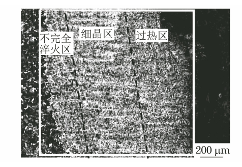
Fig. 5 Microstructure morphology of the heat affected zone
Amplified observation of the overheating region in the heat affected region shown in Fig. 5, as shown in Fig. 6, crack defects along the crystal distribution were found in the coarse martensitic tissue, which can be judged as stress fracture.
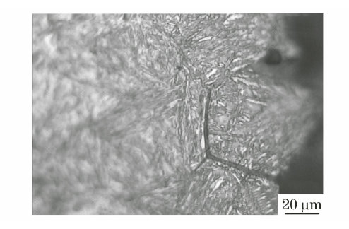
Fig. 6 Microstructure of the superheated zone of the heat affected zone
Further enlargement to observe the specimen with a weld shown in Fig. 4, as shown in Figure 7, it can be seen that at the interface of the heat affected zone and the weld zone, there is a dark welding fusing belt with a width of about 30 μm, with the phenomenon of impurity enrichment, and it can be further judged that the pin shaft fracture begins at the interface of the overheating zone and the weld zone of the heat affected zone.

Fig. 7 Microstructure morphology at the interface of the weld zone and the heat affected zone